Peru Mendivil Contact on LinkedIn

BLDC motor control for an electric scooter

Peru Mendivil · Mondragon Unibertsitatea, 2025-26

Notes

  1. Team project, five students. My part was the drive.
  2. I designed the measurement boards and characterised the motor: τ = 3.36 ms, measured on the bench.
  3. I implemented the current and speed control on an STM32. The current loop closes in τcl = 1 ms.
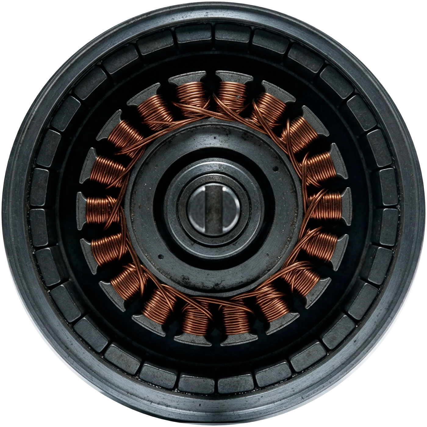
Generated photograph of an opened outer-rotor hub motor: steel rim, ring of magnets, copper winding on the stator and the axle.
Section A-A Drawing illustrative, not to scale. Photo: generated image, not my hardware.

My part of the drive

The hub motor and the IFX007T inverter were given. I designed and sized the measurement boards and did the control between them on an STM32: two PI controllers in cascade, a back-EMF feed-forward, a low-pass filter on the measured current and a speed estimate from the Hall sensors.

ItemDescriptionBy
1Magnets, 30 (15 pole pairs)given, hub motor
2Hall sensors, 3 (90 edges per turn)given, hub motor
3Stator winding, 3-phasegiven, hub motor
4Axlegiven, hub motor
5IFX007T inverter shield, 10 kHz PWMgiven
6Measurement boards: voltages, phase currents, Hall signalsPeru Mendivil
7Motor characterisation: R, L, τ, Kem, dampingPeru Mendivil
8Current and speed control on the STM32Peru Mendivil
9Battery chargerother team members

Parts list Items 1 to 4 as marked on Section A-A

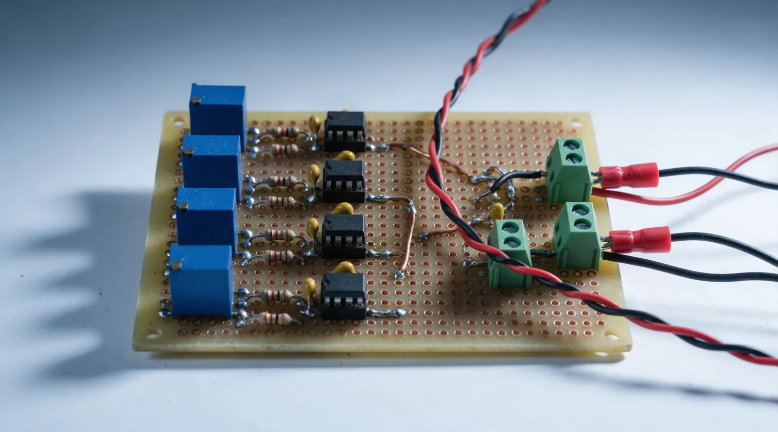
Generated image of a hand-soldered perfboard with four blue Hall-effect current sensors, resistor dividers, op-amp buffers and green screw terminals with red and black wires.
Graphic representation Generated image of the current measurement board and its components. Not a photo of the real board.

The current board carries the Hall-effect current sensors, resistor voltage dividers and op-amp buffers, soldered by hand on perfboard. To reduce electromagnetic noise I used twisted wiring, minimum loop areas between signal and ground, and a separate ground for each Hall output.

Measuring the motor

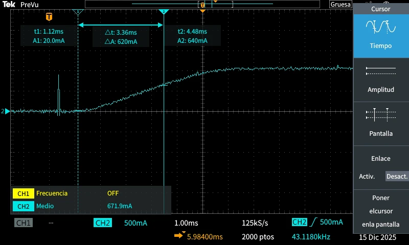
For R and L the rotor is locked, so there is no back-EMF. A voltage step then gives a first-order current response, and the time constant is the time to reach 63.2 % of the final value. I measured τ = 3.36 ms on the scope, and L = R·τ. The same test on the Simulink motor gave 3.37 ms.

With Ti = L/R the PI zero cancels the motor pole and the closed loop is first order. I chose τcl = 1 ms, ten times the period of the 10 kHz inverter, which gives Kp = L/τcl = 1.06.

Rs0.3157 Ω0.483 V / 1.02 A, rotor locked
Ls1.0607 mHL = R·τ
Kem0.0318 V·s/rad4.8 V back-EMF at 24 Hz
Detail B · Current step, normalised Dimensions in ms. Model with the measured R and L.
Tektronix capture of the locked-rotor current step with cursors 3.36 ms apart.
Scope capture Real measurement, 15 Dec 2025: Δt = 3.36 ms to 63.2 %.
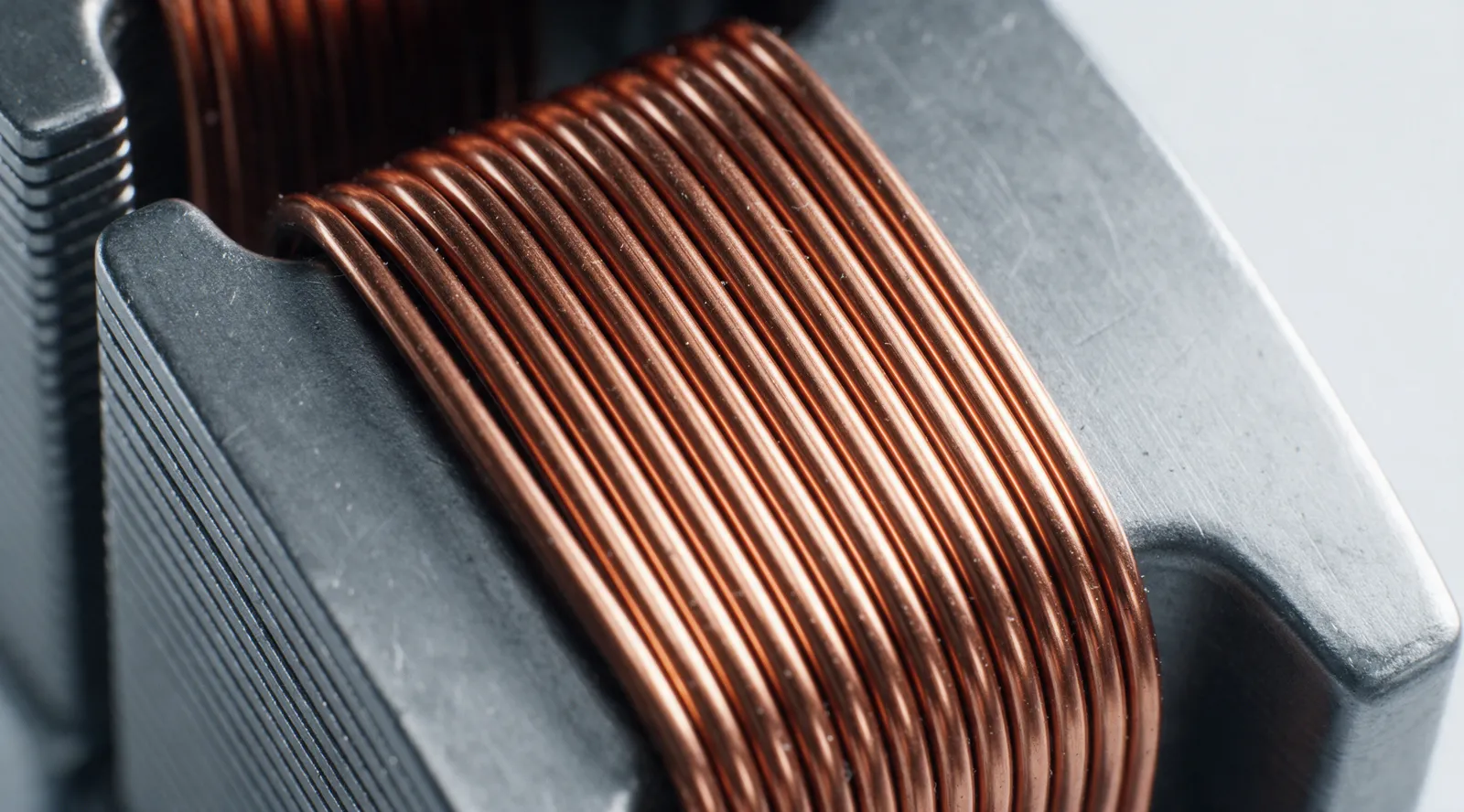
Generated close-up of copper enamel wire wound on a laminated stator tooth.
Photo reference Generated macro of a winding. Not my hardware.

Why the control runs every 0.5 ms

RevChange
AThe control first ran at 10 kHz. The speed loop measured time by counting the calls to the control function, and that count fluctuated and dropped as the scooter went faster: the STM32 could not finish the calculations in 0.1 ms. We checked it with the professor and reduced the control rate to 2 kHz (0.5 ms).

The limit of the 0.5 ms sampling

With that sampling, the current loop overshoots above Kp ≈ 2 and becomes unstable above Kp ≈ 3.9. Scroll, or move the gain on the scale.

1.06
Loop
No overshoot
Peak current
5.0 A

Unstable above Kp ≈ 3.9 with Ts = 0.5 ms

Rev B On the scooter I kept Kp = 1.06 and made Ti twenty times larger (67 ms). The response is slower, but more stable with the noise in the current measurement.

Detail C · Current step to 5 A, PI every 0.5 ms Model with the measured R and L. One grid column per control sample.

Current filter and phase margin

The phase current measured with the Hall sensors still had noise, so I added a first-order low-pass filter on the measurement. The filter adds phase lag inside the loop. Without it the phase margin is 90°. I chose the lowest cut-off that kept an acceptable margin: 250 rad/s, with 28° at 470 rad/s. In the tests, a lower cut-off made the loop unstable.
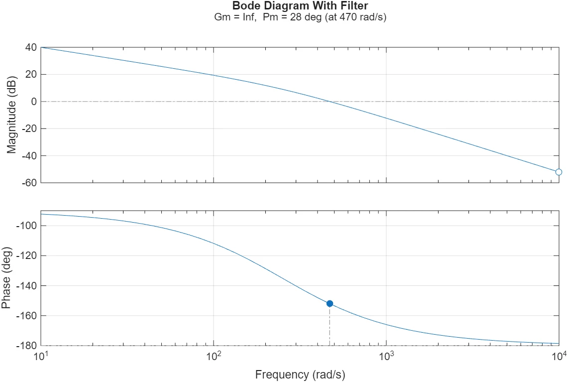
Detail D · Open-loop phase, Kp = 1.06 28° at 470 rad/s with the filter. Continuous time, as MATLAB margin() computes it.
MATLAB Bode diagram of the current loop with the filter: gain margin infinite, phase margin 28 degrees at 470 rad/s.
MATLAB figure margin(), with the 250 rad/s filter.

Speed from the Hall sensors

There is no encoder. The three Hall sensors give 6 edges per electrical cycle, so with 15 pole pairs there are 90 edges per turn. At each edge the STM32 calculates ω = (2π/90)/Δt and keeps the value until the next edge. At 200 rpm there is a new value every 3.3 ms; at 20 rpm, only every 33 ms.

The speed controller is a PI with acceleration feed-forward and anti-windup (Kp = 0.0177 A/rpm, Ti = 2.0 s). Its output is the current reference of the current loop.

Detail E · Speed seen by the controller Illustrative ramp. Edges from the model, 90 per turn.

On the scooter

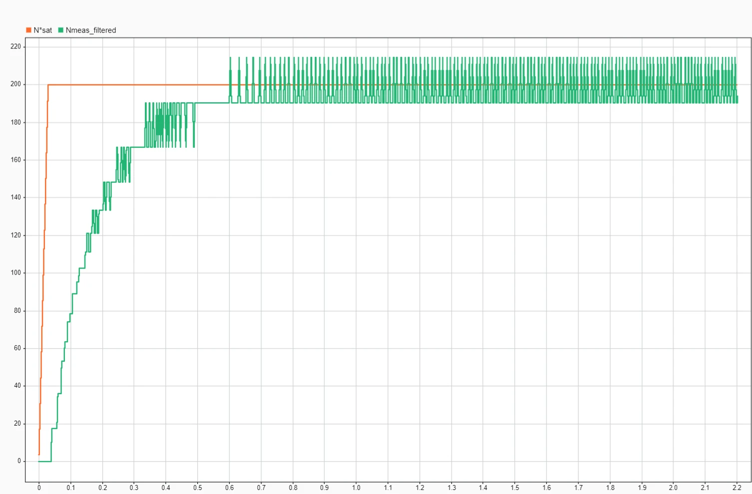
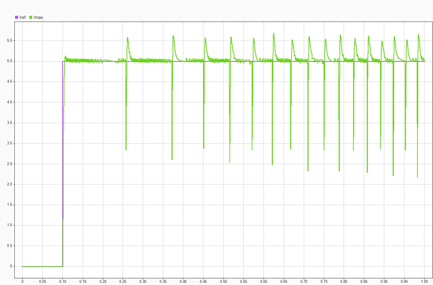
In the complete Simulink model, the current follows a 5 A step within a few milliseconds and recovers after each commutation. The speed reaches 200 rpm in about 0.6 s.

On the scooter, the drive was tested on the floor: it could be driven, accelerated and braked correctly.

20-second video summary

Simulink: 5 A current step, reference and measured current, with dips at each commutation.
Simulink, complete drive 5 A current step.
Simulink: speed reference to 200 rpm and the stepped Hall-based estimate.
Simulink, complete drive Speed to 200 rpm.
Title

Looking for a Bachelor's thesis in automation or robotics

In Västra Götaland, January to June 2027. I'm doing an Erasmus+ double degree between Mondragon Unibertsitatea and the University of Skövde.

Drawn byPeru Mendivil
PeriodJanuary to June 2027
LocationVästra Götaland
FieldAutomation or robotics
ProjectElectric scooter, Mondragon, 2025-26
SourceAnnex E, project report
ScaleNot to scale
Sheet1 of 1

Data: annex E of the project report, Mondragon Unibertsitatea, 2025-26. Charts on this page are computed in the browser from the motor model with the measured parameters. Generated images are marked as such.